

Fiber Optic Transport & FTTH Backbones
OPTICAL NETWORK ENGINEERING
Connecting Networks Through Engineered Optical Paths
Fiber-optic infrastructure supports high-capacity connectivity between network sites, buildings and access subscribers. The appropriate solution depends on distance, topology, available fiber, optical power budget, transmission requirements and resilience objectives.
Novatelia's published optical infrastructure scope includes wavelength-division multiplexing, passive optical access networks, fiber backbone planning, connectivity components and project-specific testing requirements.
- Transport NetworksCWDM and DWDM channel plans over fiber that has been checked for the path.
- Passive Optical AccessGPON or XGS-PON from an OLT through splitters to ONT or ONU endpoints.
- Optical Protection & ValidationDiverse routes where specified, and the tests the contract actually requires.
WHERE OPTICAL INFRASTRUCTURE OPERATES
Fiber Networks Across Critical Environments
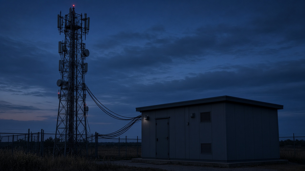
Telecom Service Providers
Optical backbone and access infrastructure supporting provider network expansion and subscriber connectivity.
Utility Transmission Routes
Fiber connectivity along utility corridors and distributed infrastructure, subject to route and operational requirements.
Campus Inter-Building Links
Optical backbone connections between buildings, equipment rooms and enterprise network distribution points.

Industrial Corridors
Fiber routes connecting facilities, network cabinets, monitoring systems and distributed operational sites.
INTERACTIVE OPTICAL ARCHITECTURE
Explore the Layers of an Optical Network
WDM multiplexer
Combines distinct wavelength channels onto one fiber. It does not create those wavelengths by itself.
CWDM / DWDM transport
Wavelength allocation, optical budget, dispersion and OSNR requirements depend on equipment and transmission design. Amplifiers are included only when the path needs them.
- Client signal
- The service handed to the optical system. It stays a client signal until a transponder or muxponder is required to adapt it.
- Transponder or muxponder
- Used where the client signal must be adapted to a wavelength. A passive multiplexer is not a transponder.
- WDM multiplexer
- Combines distinct wavelength channels onto one fiber. It does not create those wavelengths by itself.
- Fiber span
- The optical path between sites. Distance and loss are properties of that path, not a fixed product figure.
- Optical amplifier
- An intermediate amplifier is shown only where the optical budget needs it. It is not part of every link.
- WDM demultiplexer
- Separates the wavelength channels at the far end.
- Receiving equipment
- Compatible receiving optics or a transponder, matched to the channel plan.
GPON / XGS-PON access
The OLT, feeder, splitter, and ONT form a point-to-multipoint optical distribution network. Conventional GPON uses lower, asymmetric line rates. XGS-PON is a nominal symmetric 10G-capable access technology. Delivered throughput depends on the split, the optical budget, and how the service is provisioned. Subscribers do not all receive the full nominal line rate at the same time.
- OLT
- The optical line terminal is the head-end of the passive optical network. It serves many endpoints through the optical distribution network.
- Feeder fiber
- The fiber from the OLT toward the first splitter.
- Passive splitter
- A passive split shares the optical signal. Example ratios such as 1:32 or 1:64 are design choices, not a promised subscriber count.
- Distribution and drop fiber
- Fiber from the splitter toward each optical network unit or terminal.
- ONU / ONT
- The endpoint at the subscriber or building. It terminates the passive optical network.
Protection paths
Protection switching behavior, restoration time and availability depend on the optical architecture, equipment capabilities and fault conditions.
- Primary route
- The working optical path between the two endpoints in this example.
- Alternative route
- A second physical path. Route diversity exists in this drawing only because the two paths are shown as separate.
- Protection equipment
- Protection switching behavior, restoration time and availability depend on the optical architecture, equipment capabilities and fault conditions.
- Endpoints
- The two sites the protected link joins. Recovery behavior is not stated as a universal time.
OPTICAL TRANSPORT
Expand Fiber Capacity Through Wavelength Multiplexing
CWDM and DWDM technologies can carry multiple optical channels over suitable fiber infrastructure. The number of channels, channel spacing, required transponders, optical amplification and achievable distances depend on system design and equipment compatibility.
CWDM uses wider channel spacing and is often considered for shorter, simpler reaches. DWDM uses tighter spacing and can support larger channel counts when the fiber, the optics, and any amplification are designed together. Passive multiplexers, active transponders, and dark fiber are separate decisions. Wavelength multiplexing does not remove the need for a new fiber route when the existing fiber is unsuitable.
Conceptual wavelengths only. This drawing is not a channel count or a measured spectrum.
FTTH & PON ARCHITECTURE
Passive Optical Networks for Distributed Access
Passive optical network architectures connect an optical line terminal to multiple optical network units through an optical distribution network. Technology selection and splitter planning must account for service demand, optical budgets, equipment interoperability and network expansion.
GPON
Conventional GPON is a passive optical access technology with lower, asymmetric line rates. It is not a symmetric 10G service. The OLT, the split, and the optical budget decide what the design can support.
XGS-PON
XGS-PON is specified for nominal symmetric 10G operation. The rate a subscriber receives still depends on provisioning, split ratio, optical reach, and contention. A nominal line rate is not a throughput promise.
- OLT at the head-end.
- ONT or ONU at the endpoint.
- Passive optical splitters in the distribution network.
- Feeder fiber and distribution fiber.
- Optical reach and power budget for the chosen split.
- Subscriber density as an input, not a fixed ratio.
RESILIENT OPTICAL PATHS
Protection Strategies for Critical Fiber Links
Critical optical connections may require alternative fiber routes, protection equipment and defined recovery behavior. Route diversity, failure scenarios and restoration objectives must be evaluated for each project.
Primary and alternate routes
Two paths are diverse only when they do not share the same physical route. A second wavelength on the same cable is not a diverse route.
Detection and restoration
Fault detection and restoration testing are scoped with the protection equipment. Restoration time is an equipment and design outcome, not a figure published on this page.
OPTICAL PATH ENGINEERING
Every Optical Link Begins With a Power Budget
Optical link planning considers transmitter output, receiver sensitivity, fiber attenuation, connector loss, splice loss, passive component loss and engineering margin.
Estimated Path Loss = Fiber Loss + Connector Loss + Splice Loss + Passive Component Loss + Other Applicable Losses
- Fiber length and the attenuation coefficient for that fiber type.
- Connector count and splice count.
- Splitter loss where a passive splitter is in the path.
- Optical margin kept for the design.
- Transceiver compatibility with the fiber and the channel.
Estimated design loss, the available optical budget, and the loss measured after installation are three different results. This page does not calculate a certified budget.
PHYSICAL FIBER INFRASTRUCTURE
Precision in Every Connection
- ODF and fiber distribution frames.
- Patch panels and optical connectors matched to the cable.
- Fusion splicing where the route is jointed.
- Fiber cable routing with bend limits respected.
- MPO/MTP connections where the design uses multi-fiber connectors.
- Connector inspection and cleaning before test.
- Labeling and documentation of each path.
OPTICAL VALIDATION
From Installation to Verified Test Results
Optical Loss Testing
Measurement of insertion loss using appropriate light-source and power-meter procedures.
OTDR Testing
Trace-based characterization of optical events and fiber path characteristics, where suitable for the project. A trace alone is not universal fiber certification.
Connector Inspection
End-face examination and cleanliness assessment. IEC 61300-3-35:2022 is the inspection reference for connector end faces. Inspection does not replace attenuation and return-loss measurement, and it is not a Novatelia certification.
Documentation
Recording measured results, identified events, cable references and relevant project acceptance criteria. Acceptance thresholds have to be defined. Bidirectional testing is used when the specification requires it.
Testing requirements are contract-dependent. A completed inspection is not, by itself, a certified link.
DESIGN & HANDOVER DOCUMENTS
Documentation That Supports Procurement and Implementation
The final deliverables are determined by the agreed engineering, installation and testing scope.
01 — Optical Network Architecture Diagram
The transport, access, or protection topology agreed for the project.
02 — Fiber Route & Connectivity Schedule
Paths, fiber counts, and the connections the installation has to follow.
03 — Wavelength Allocation Plan
Channel assignments when wavelength multiplexing is part of the design.
04 — Optical Link Budget Calculation
An estimated loss budget for the paths in scope, distinct from a measured result.
05 — Splitter & ODN Layout
Splitter locations and distribution fiber when a passive optical network is included.
06 — Test & Inspection Records
The measurements and inspections named in the contract. A record is not automatically a certified link.
ASSOCIATED ENGINEERING SERVICES
Professional Services Across the Fiber Lifecycle
Technical Assessment & BOM/BOQ Review
Review of a route, a bill of materials, and the optical assumptions before equipment is ordered.
Fiber Optic & Structured Cabling
Optical and copper installation, patching, and pathways within the agreed scope.
Testing, Validation & Handover
The optical tests and handover records named for the project.
PREPARE YOUR OPTICAL REQUIREMENT
What Information Is Needed for Fiber Network Design?
The RFQ page keeps a browser draft. It does not add a file upload. Drawings and reports can be described in that draft and shared through the contact already published for the enquiry.
- Start and endpoint locations.
- Approximate fiber route length.
- Existing fiber type and available strands.
- Required data rates.
- Number of services or subscribers.
- Existing OLT, ONT, or transceiver equipment.
- Available optical budget information.
- Planned splitter ratios.
- Required fiber redundancy.
- Existing OTDR or optical loss reports.
- Physical route constraints.
- Expansion requirements.
OPTICAL NETWORK QUESTIONS
Fiber Optic Transport — Frequently Asked Questions
What is the difference between CWDM and DWDM?
Both technologies carry multiple optical wavelength channels over fiber. They differ in channel spacing, system characteristics and typical deployment requirements. The appropriate choice depends on capacity, distance and equipment compatibility.
What is the difference between GPON and XGS-PON?
GPON and XGS-PON are passive optical access technologies with different line-rate capabilities. XGS-PON supports nominal symmetric 10G operation, while conventional GPON commonly uses lower, asymmetric line rates.
Can existing dark fiber support WDM?
Existing dark fiber may be suitable for wavelength multiplexing after relevant fiber characteristics, optical loss, distance and equipment requirements have been evaluated.
What determines the maximum fiber link distance?
Maximum distance depends on the optical equipment, fiber type, attenuation, dispersion, intermediate components and available system margin.
Does an OTDR result certify a complete fiber link?
Not by itself. The required acceptance process depends on the link specification, test methods and agreed performance criteria.
Can Novatelia prepare a fiber BOM?
A project-specific equipment and materials schedule can be prepared as part of an agreed design or quotation process using the relevant route and technical requirements.
RELATED INFRASTRUCTURE
Explore Connected Technology Solutions
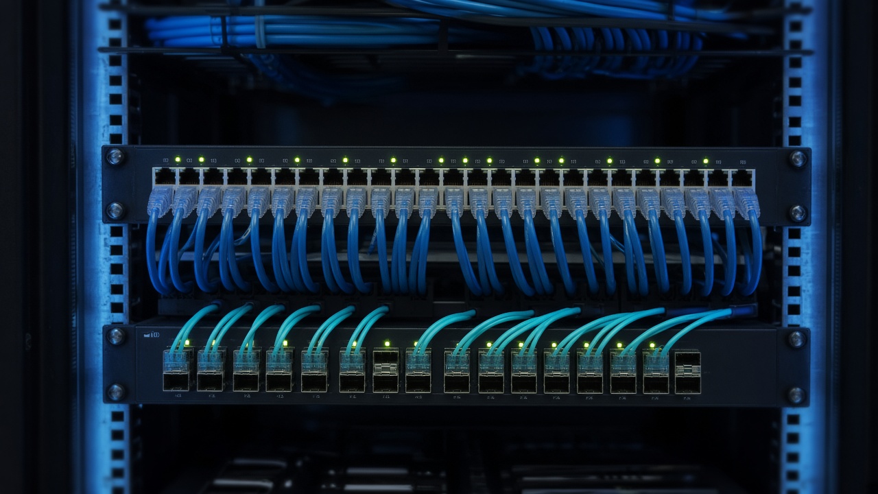
Enterprise Campus Networking
Campus switching that uses the optical backbone between buildings.
Telecom & ISP Infrastructure
Provider routing and backhaul, separate from the optical access design on this page.

Data Center Infrastructure
Rack and fabric infrastructure that optical links connect.
Related note: SR vs LR SFP+: 10G Optical Link Comparison. That article compares module types. It does not set a distance guarantee for a Novatelia design.
PLAN YOUR OPTICAL NETWORK
Ready to Build Your Fiber Infrastructure?
Share your fiber route, optical transport requirements, equipment list or technical drawings with Novatelia for an initial project review.
Opening the RFQ page keeps a browser draft. It does not submit a quotation or issue a reference.