Fiber Optic & Structured Cabling Services
Fiber & Cabling Infrastructure for Reliable Network Connectivity
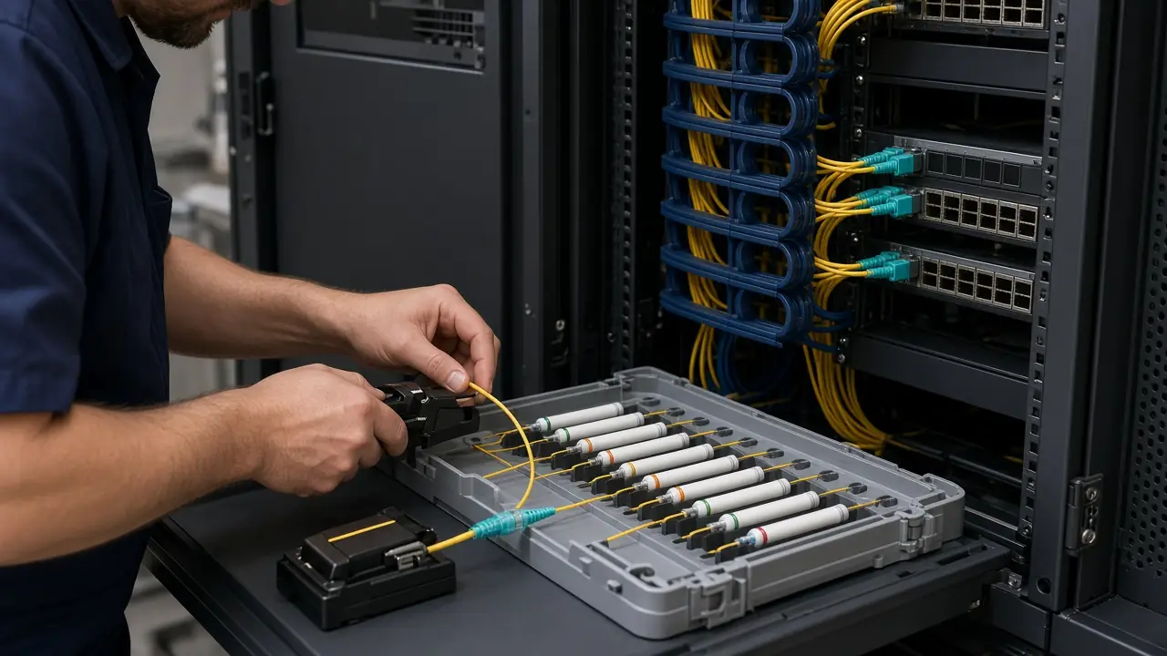
Novatelia supports fiber optic and structured cabling projects for enterprise, data center, campus, building and industrial infrastructure. Depending on project scope, services may include cable installation, termination, fiber splicing, patching, labeling, defined testing and handover documentation.
The exact cabling method, media, interfaces, routing, termination and testing requirements depend on the approved design, environment, distances, equipment and project specifications. Novatelia provides this work in Oman for infrastructure projects. General equipment installation stays on Professional Installation. Formal project acceptance is a later stage.
- Plan
- Install
- Terminate
- Splice
- Patch
- Test
- Label
- Handover
Fiber & Structured Cabling Infrastructure
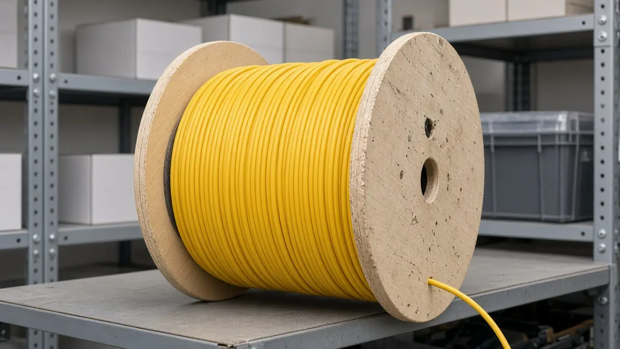
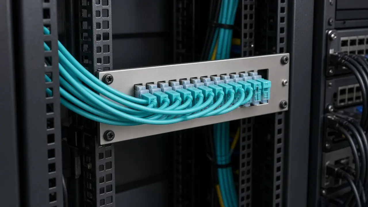
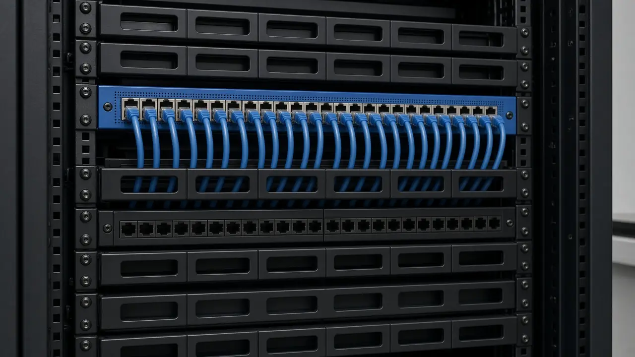
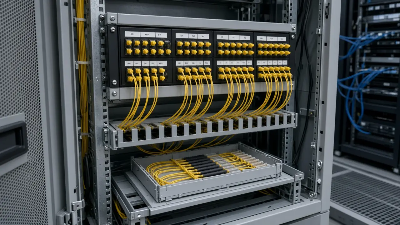
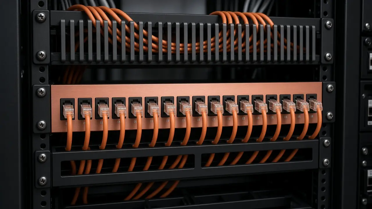
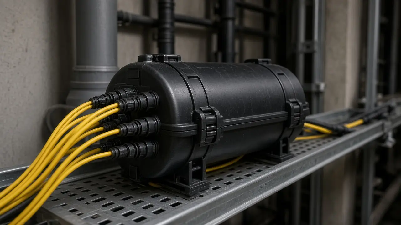
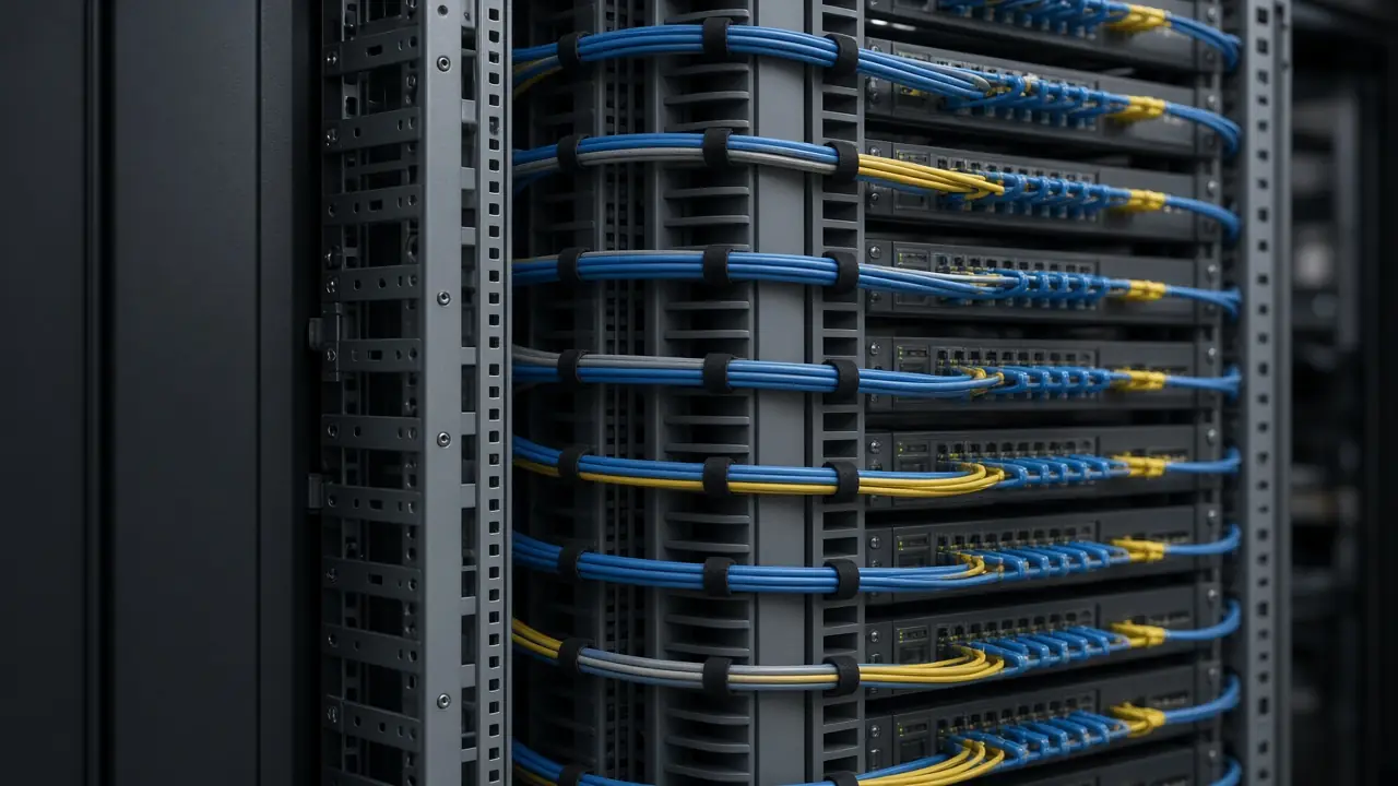
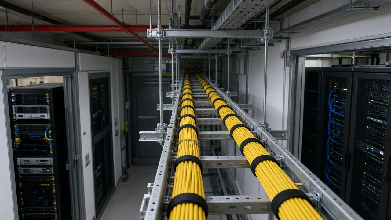
Project-defined optical infrastructure for the distances and interfaces named in the approved design. Fiber class, wavelength, and loss budget are not assumed on this page.
How Fiber Connects the Infrastructure
Conceptual fiber infrastructure model
The diagram shows source, path, distribution, termination, and destination. It does not mean every project uses this topology.
The main distribution point where backbone fiber is presented, often at an ODF.
A campus reading of the same idea is Building A, then an ODF, then the fiber backbone, then an ODF, then Building B. That reading is also conceptual.
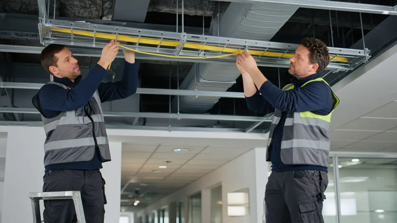
Fiber Optic Cable Installation
Where the scope includes it: route review, path preparation, fiber pulling, indoor deployment, outdoor deployment, backbone installation, building-to-building connectivity, rack or ODF entry, protection, bend-radius care, slack, identification, and labeling.
Cable fire rating, armoring, UV rating, rodent resistance, water blocking, and any classification of the jacket are product and project facts. They are not stated here.
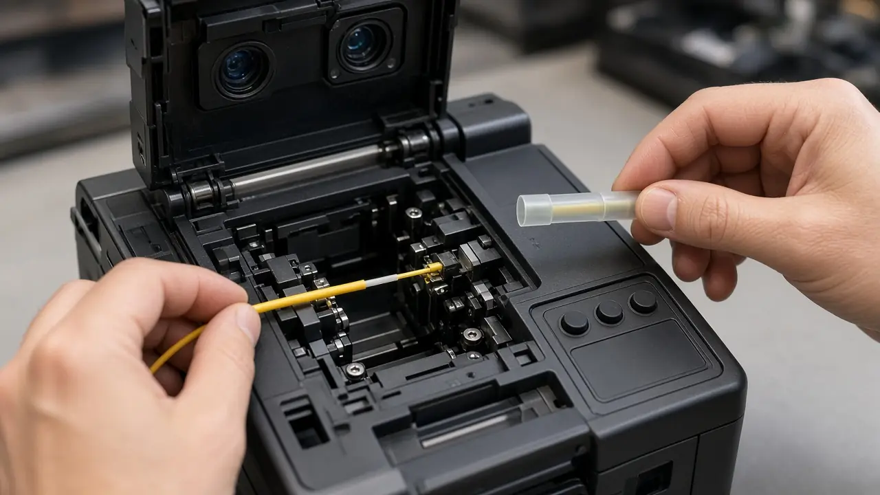
Fiber Splicing & Termination
Where scoped: fusion splicing, pigtail splicing, ODF termination, fiber-panel termination, splice-tray organization, splice protection, a connectorized handover, and the patch-cord interface. LC or SC is used when the specification names it.
Fusion splicing where that method is specified. No splice-loss number is published without a measurement.
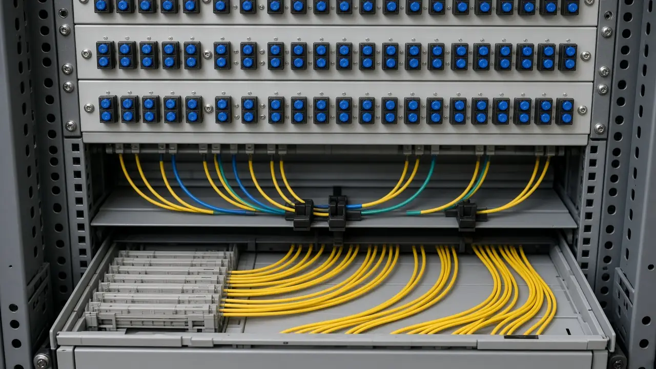
Optical Distribution & Fiber Panel Integration
Where scoped: ODF installation, panel preparation, adapter placement, pigtail organization, splice-tray organization, fiber routing, patch-cord connection, port identification, and labeling.
Conceptually the backbone arrives at the ODF, a port or adapter presents it, and a patch cord continues to the network equipment. This section is not a product catalog.
Structured Copper Cabling
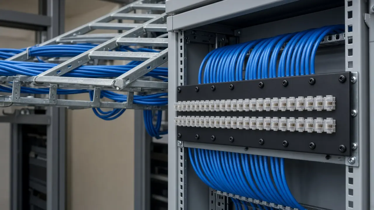
Where scoped: cable routing, horizontal cabling, patch-panel termination, outlet termination, rack-side termination, patch-cord integration, cable management, labeling, and defined testing.
Cat6 or Cat6A is relevant only when the specification asks for that category. A continuity check is not a Cat6 or Cat6A certification, and it is not a permanent-link or channel result.
MDF, IDF & Rack Connectivity
Conceptual model
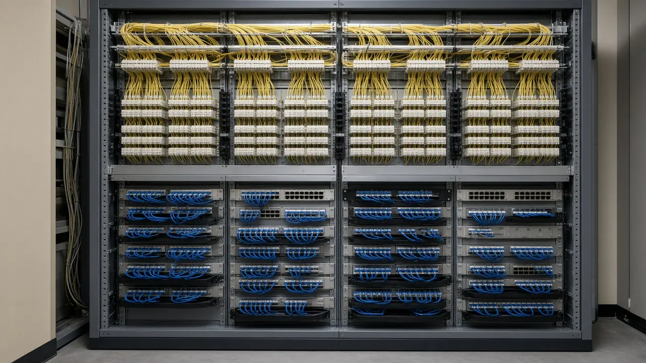
The relationships are core or MDF, fiber backbone, IDF, access switch, copper or fiber access, and the endpoint. An ODF and a patch panel sit where the design places them. This is not a drawing of a specific customer.
Data Center Fiber & Copper Cabling
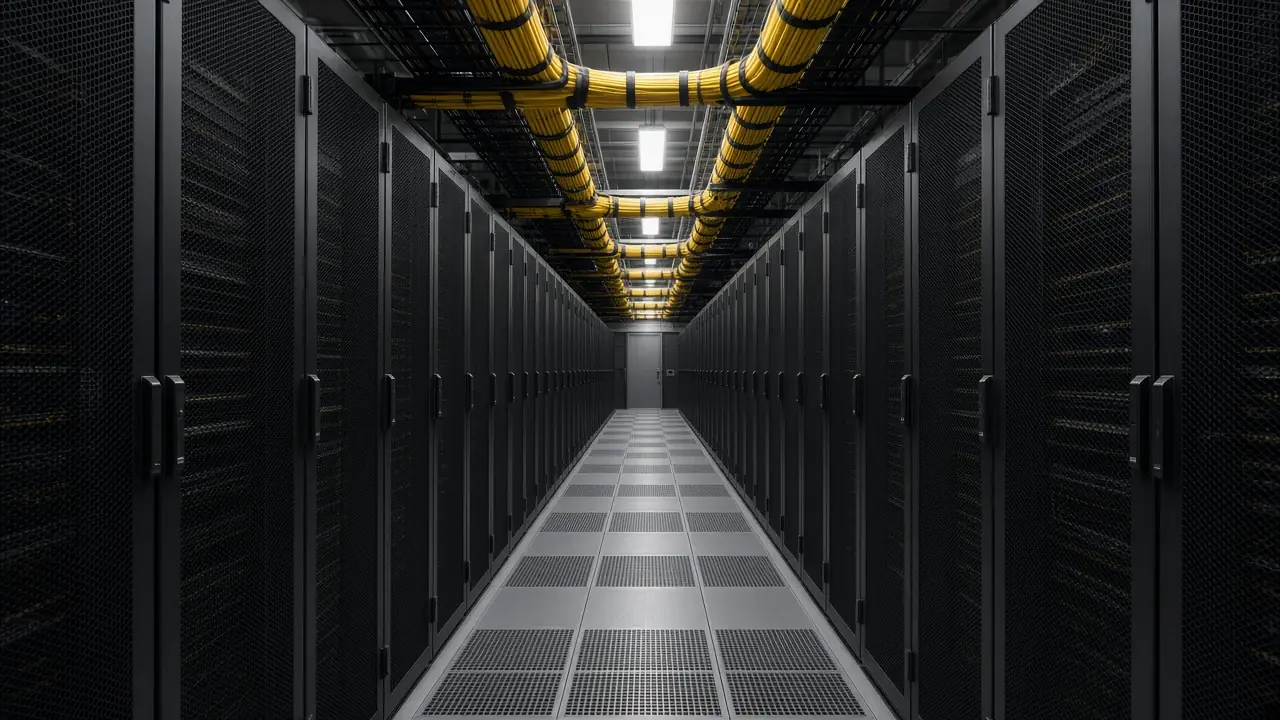
Where scoped: rack-to-rack connectivity, fiber patching, copper patching, ODF or patch-panel integration, equipment uplinks, routing, cable management, port identification, labeling, and documentation.
Related page: Data center solutions. No tier rating and no data-center certification is claimed.
Campus & Building Backbone Connectivity
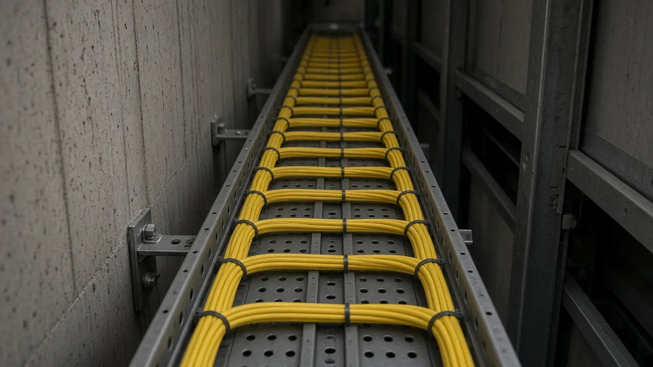
Where scoped: MDF-to-IDF backbone, floor distribution, building-to-building fiber, riser connectivity, access-layer cabling, ODF distribution, rack integration, labeling, and defined testing.
A core can feed an MDF, then a fiber backbone, then more than one IDF and its access layer. That shape is an illustration, not a universal campus.
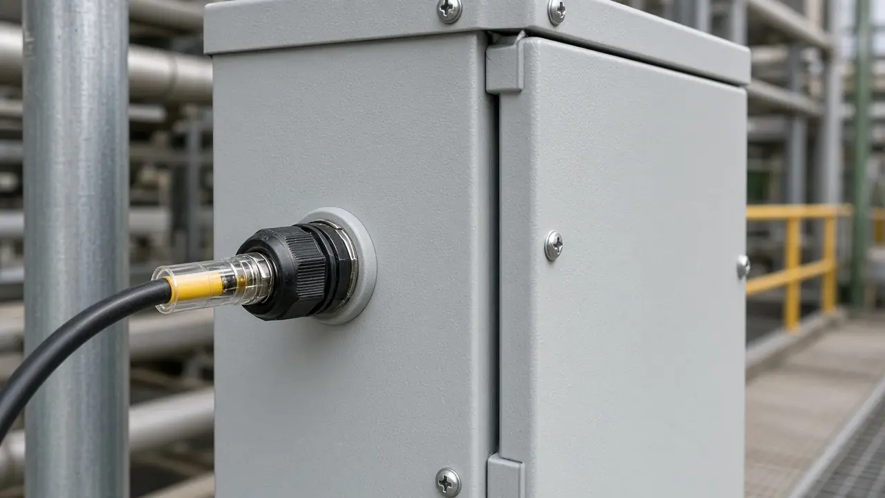
Industrial & Outdoor Fiber Connectivity
Where the project supports it: outdoor fiber routing, industrial connectivity, protected cable routing, a longer backbone, building-to-building connectivity, and ruggedized components when they are specified.
Hazardous-area, explosion-protection, marine, or oil-and-gas product claims are not made on this page.
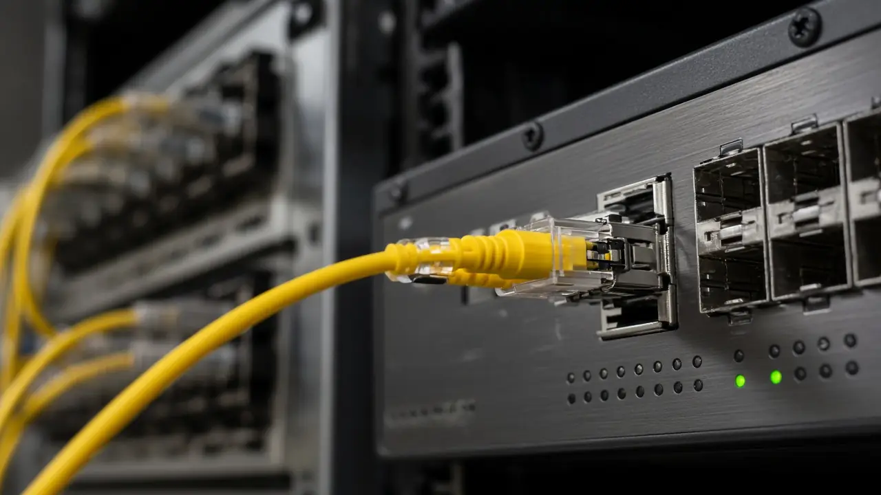
Fiber Patching & Optical Interfaces
The chain is fiber, connector, patch panel or ODF, patch cord, optical module, and network port. Considerations can include connector type, fiber type, the module, interface speed, wavelength, distance, the patch cord, and polarity where it applies.
Connector shape does not decide module compatibility. Nothing on this page is described as universal or compatible with every switch.
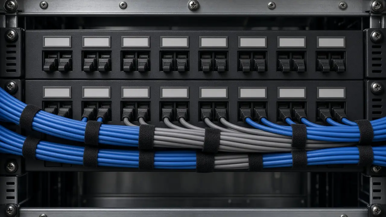
Cable Management & Infrastructure Labeling
Where scoped: routing, velcro management, rack organization, ODF labels, patch-panel labels, port labels, cable IDs, MDF and IDF identifiers, link IDs, and endpoint labels.
Clear physical organization and consistent identification help make testing, troubleshooting, handover and later maintenance more manageable. Labeling should follow the approved project naming scheme.
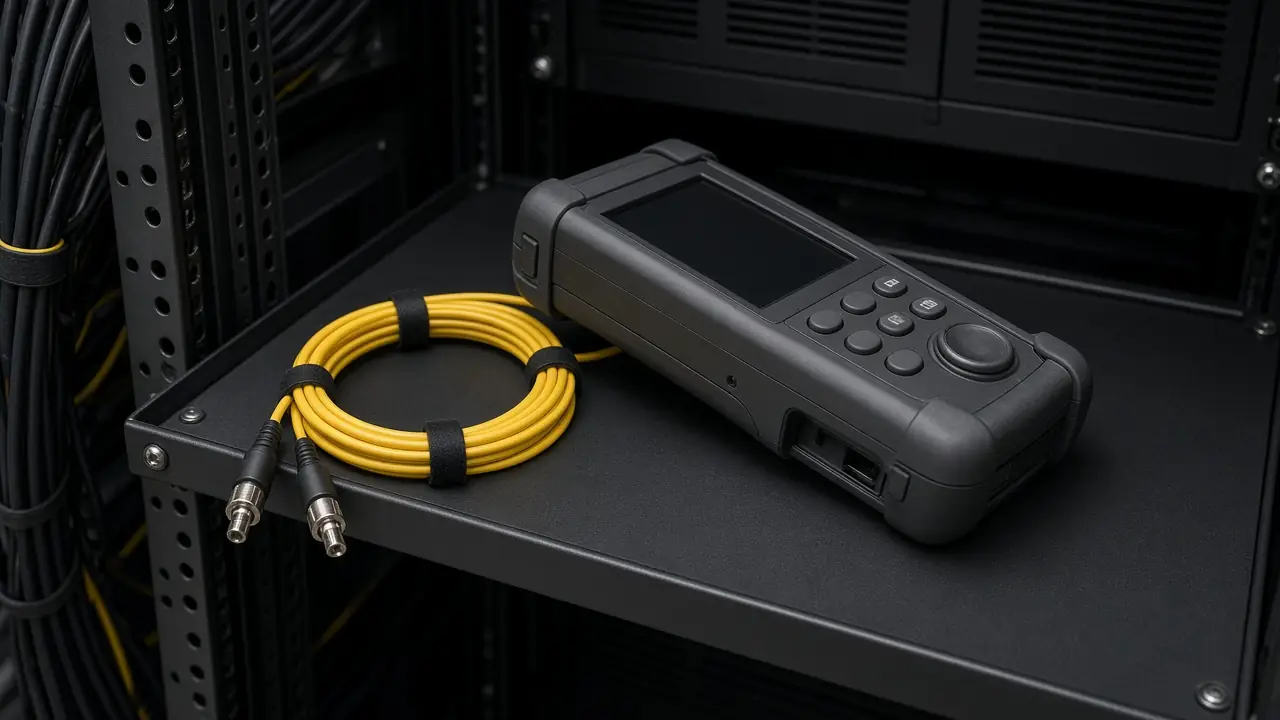
Fiber Testing & OTDR Validation
Where in scope: continuity, optical power, insertion-loss measurement, OTDR, event identification, length, splice-event review, connector-event review, and preparation of the test record.
OTDR can help characterize events and distance along an optical link. Power and loss testing and OTDR serve different purposes. This page does not publish a pass, a loss budget, or a standard result. A result needs the method, the limit or reference, the instrument, and the measured value.
Conceptual OTDR interpretation
- Tester
- Fiber link
- Connector
- Splice
- Fiber
- End
A trace is read for distance, event, loss, and reflection. No customer trace is shown here.
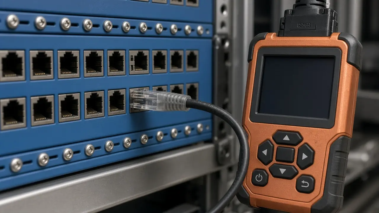
Copper Cabling Testing
Where applicable: wiremap, continuity, length, pair integrity, and fault identification.
Certification testing is a separate method. It exists only when the equipment, the standard, the limit, the adapter, and an actual result exist. A continuity tester does not make a certified Cat6 or Cat6A installation.
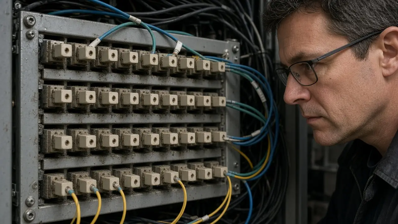
Can Existing Fiber or Cabling Be Assessed?
Existing fiber or copper infrastructure may be reviewed where the route, termination, condition, labeling and available test information can be accessed. The appropriate assessment method depends on the type of cabling and the question being investigated.
- Visual inspection
- Route review
- Termination review
- Label review
- Continuity
- Fiber test
- OTDR
- Copper testing
Existing cabling is not treated as reusable until that check is done.
What We Need Before Cabling Work Starts
- Site information
- Drawings
- Cable schedule
- MDF / IDF locations
- Rack locations
- Route information
- Link distances
- Fiber type if specified
- Copper category if specified
- Connector requirements
- ODF / patch panel requirements
- Endpoint count
- Equipment interfaces
- Testing requirement
- Labeling standard
- Handover requirement
- Site access conditions
Where project information is incomplete, cabling requirements should be clarified before installation rather than inferred from assumptions.
From Cabling Requirement to Handover
Installation
Input. An agreed route and materials.
Action. Install the scoped cable.
Output. Cable in place, not yet a tested link.
Typical Fiber & Cabling Project Outputs
Depending on project scope:
- Installed cabling
- Terminated fiber
- Completed splices
- ODF / patch panel integration
- Cable labels
- Port labels
- Link identification
- Fiber test records
- OTDR records where included
- Copper test records where included
- Issue / exception list
- Cable schedule
- Link schedule
- As-built information where included
- Handover documentation
Common Fiber & Cabling Projects
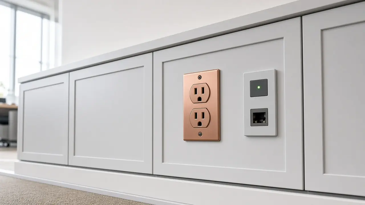
Office / enterprise network
MDF, backbone, IDF, access, outlets
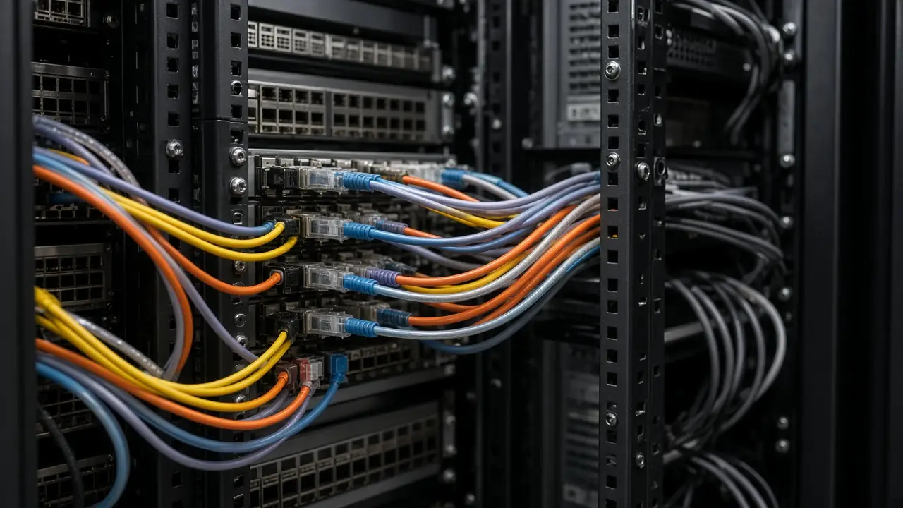
Data center
Rack, fiber or copper, patch panel, equipment, test
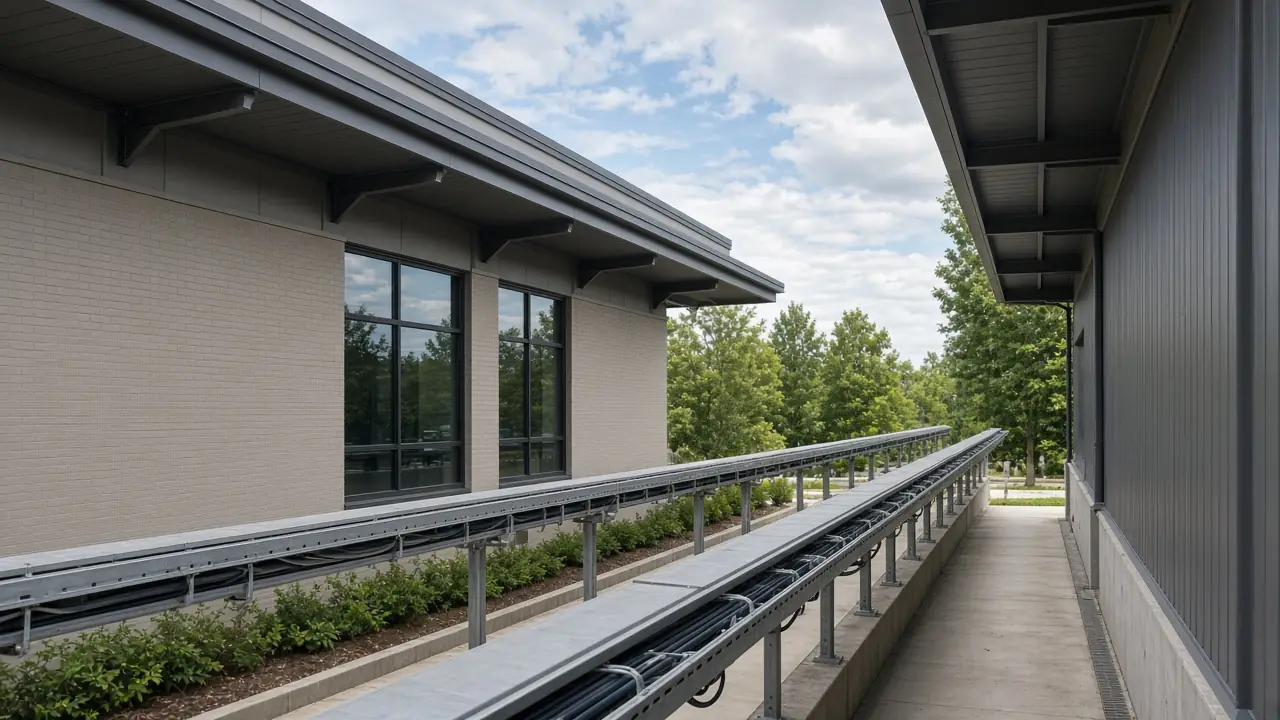
Campus / multi-building
Building A, ODF, backbone, ODF, Building B
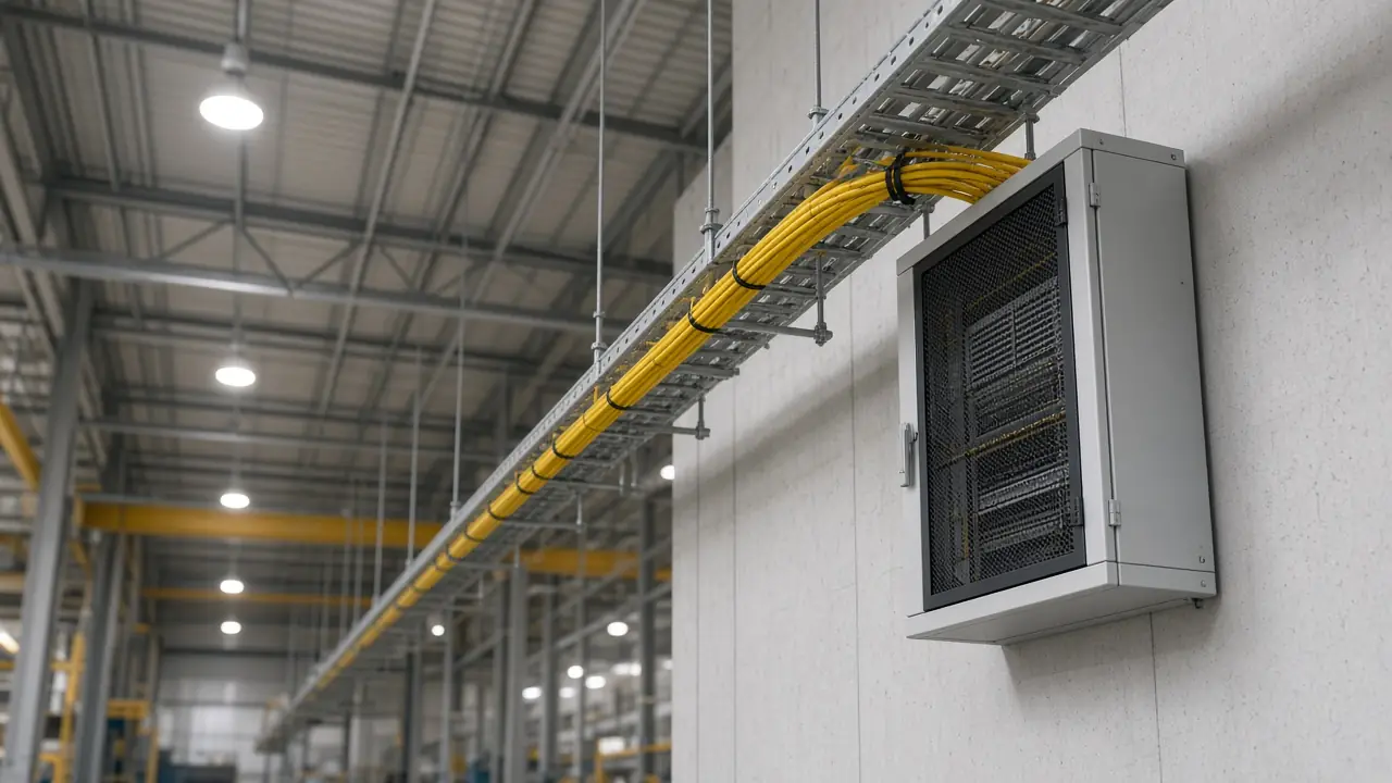
Warehouse / large facility
Core, fiber backbone, distribution, access
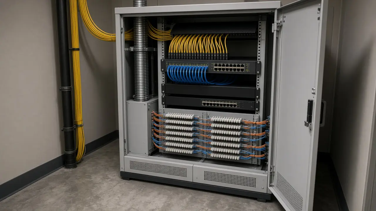
Hotel / multi-story building
MDF, floor IDF, fiber or copper distribution, connected systems
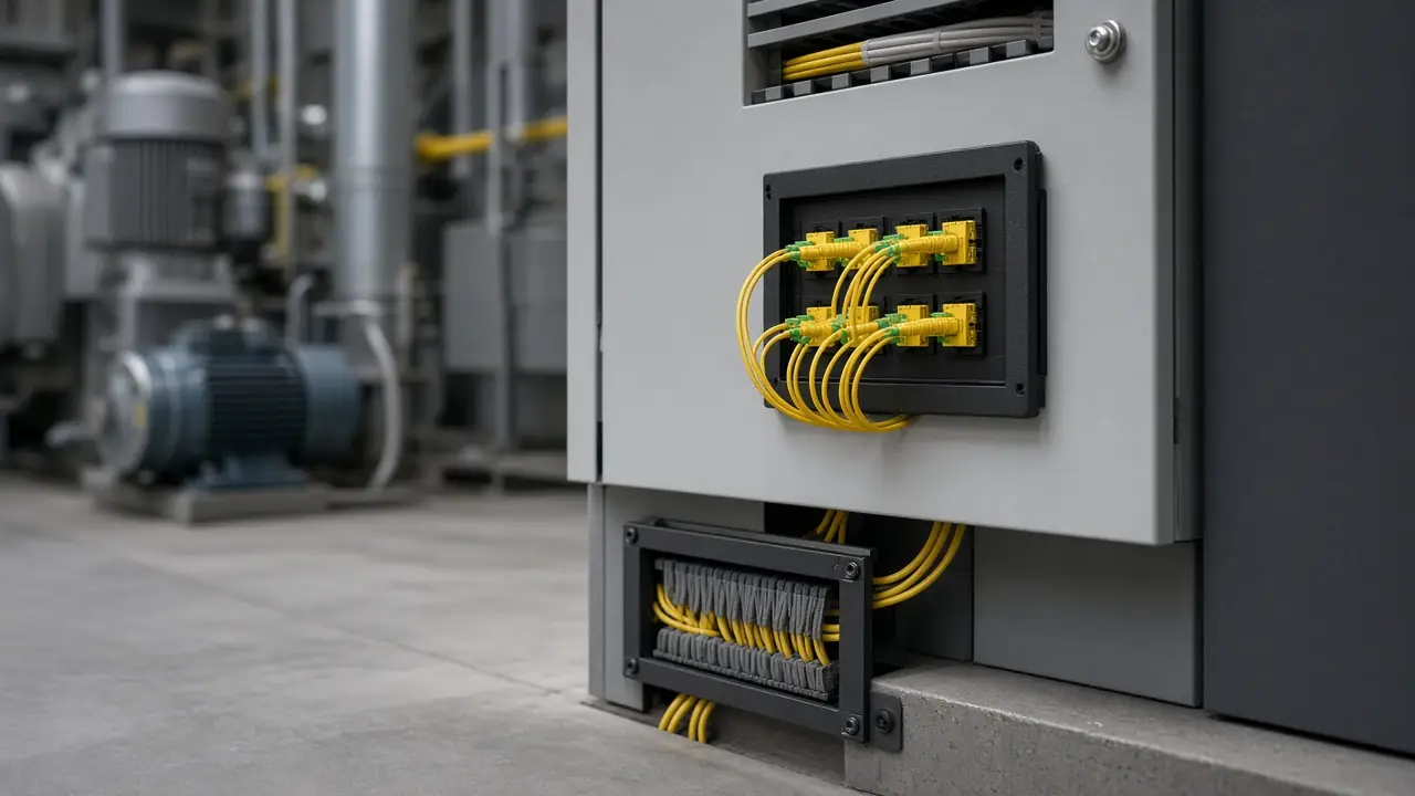
Industrial site
Core, protected route, fiber, remote distribution, network equipment
What Cabling Installation Does — and Does Not Prove
Cabling work can include
- Cable installation
- Fiber splicing
- Termination
- ODF integration
- Patch-panel integration
- Patching
- Labeling
- Defined fiber testing
- Defined copper testing
- Documentation
It does not automatically prove
- Application performance
- Network performance
- Wireless coverage
- Security compliance
- Full system interoperability
- Carrier service quality
- Final project acceptance
- Standards certification
- Cat6 or Cat6A certification
- Fiber loss-budget compliance
- Data-center tier compliance
Those outcomes are proven only when the relevant test or evidence specifically proves them.
Cabling Is Followed by Validation & Acceptance
- Install
- Terminate
- Cabling-specific test
- Remediate if required
- System validation
- Project acceptance
- Handover
Fiber and cabling installation is not considered formally accepted merely because physical installation is complete. Acceptance depends on the testing and project criteria defined for the scope.
Cabling-specific tests stay with this service. Broader testing, validation, and acceptance is a later service and is not linked here because that page is not published. Related pages that do exist: network design, professional installation, enterprise networking, and fiber optic transport.
Evidence & Delivery Readiness
- This published service scope
Proves: The cabling activities Novatelia describes for a scoped project.
Does not prove: It does not prove a named customer installation or a test result.
- Photographs on this page
Proves: The kind of physical work the sections describe.
Does not prove: They are not a Novatelia project record, not a customer site, and not a test trace.
- Defined test records, when the scope includes them
Proves: The method that was actually run, and only the values that were measured.
Does not prove: A record does not certify a standard, a category, or project acceptance by itself.
Fiber Optic & Structured Cabling — Questions & Answers
What is included in fiber optic installation?
Depending on project scope, fiber installation may include route preparation, cable installation, termination, splicing, ODF integration, patching, labeling, defined testing and handover documentation.
Scope: Only the activities named for that project.
Condition: The design, route, and hardware have to be known.
Limitation: Installation is not formal acceptance.
Can Novatelia splice and terminate fiber?
Fiber splicing and termination can be included where required by the project. The exact method depends on the cable, termination hardware, connector requirements and approved design.
Scope: Splices and terminations in the approved scope.
Condition: Connector type follows the specification.
Limitation: A splice-loss figure is not stated without a measurement.
Does Novatelia provide OTDR testing?
OTDR testing may be included where required by the project. OTDR can help identify distance and events along an optical link. It does not by itself prove every acceptance requirement.
Scope: OTDR only when the scope includes it.
Condition: The link has to be accessible to the instrument.
Limitation: An OTDR trace is not a loss-budget pass and not project acceptance.
What is the difference between single-mode and multimode fiber?
Single-mode and multimode fiber are different optical media used for different link and equipment requirements. The correct fiber type should be selected from the approved design, distance, interfaces and project specification rather than assumed.
Scope: Media selection for the link.
Condition: Distance and interfaces come from the design.
Limitation: This page does not assign a class, wavelength, or distance rating.
Can Novatelia install structured cabling?
Structured copper cabling can be included in project scope, including cable routing, patch-panel and outlet termination, labeling and defined testing.
Scope: Copper cabling named in the scope.
Condition: Routes, panels, and outlets are defined.
Limitation: Continuity is not category certification.
Do you provide Cat6 and Cat6A cabling?
Cat6 or Cat6A cabling can be considered where required by the project specification. The installed category and any certification claim must be supported by the actual materials, installation and required test method.
Scope: The category the specification names.
Condition: Materials and the test method have to match that claim.
Limitation: Naming Cat6 or Cat6A on a page is not a certification.
Can Novatelia install ODFs and patch panels?
ODF and patch-panel installation and integration can be included as part of the fiber or structured cabling scope, depending on the approved infrastructure design.
Scope: Panels the design places.
Condition: Port counts and adapter types come from the schedule.
Limitation: This is not a product catalog.
Next: Share the panel schedule
Can multiple buildings be connected with fiber?
Building-to-building fiber can be part of a campus or facility backbone where the route, distance, cable type, termination, protection and interfaces are defined for the project.
Scope: A backbone the project defines.
Condition: The route and protection have to be specified.
Limitation: The sample topology on this page is not every campus.
Next: Share the campus route
What testing is required after fiber installation?
The required testing depends on the project acceptance criteria. It may include continuity, optical power or insertion-loss measurement and OTDR testing. The appropriate method should be defined by the scope rather than assumed.
Scope: The methods the criteria name.
Condition: Method, limit, and instrument are part of a result.
Limitation: No method is declared a pass on this page.
What documentation can be provided after cabling work?
Depending on scope, documentation may include cable and port labels, link schedules, fiber or copper test records, exception lists and as-built information.
Scope: Records the scope includes.
Condition: A record is produced for work that was done.
Limitation: Not every project receives every record.
Next: Name the handover set
Can Novatelia support data center cabling?
Data-center cabling may include rack-to-rack fiber or copper connectivity, patch-panel or ODF integration, patching, cable management, labeling and defined testing according to the project scope.
Scope: In-room cabling the design defines.
Condition: Rack positions and interfaces are known.
Limitation: No tier or data-center certification is claimed.
Next: Share the rack layout
Can existing fiber be tested before reuse?
Existing fiber can be assessed where accessible. The appropriate checks may include visual inspection, continuity, optical testing or OTDR depending on the condition and question being investigated.
Scope: Plant that can be reached.
Condition: Access to the route and the ends is required.
Limitation: Reuse is not assumed before the check.
What information is needed before cabling starts?
Useful inputs include drawings, cable schedules, MDF and IDF locations, rack positions, route information, link distances, media and connector requirements, endpoint counts, labeling requirements and the required testing method.
Scope: The facts the scoped work will use.
Condition: Missing facts are asked for.
Limitation: Gaps are not filled by assumption.
Does cable installation mean the link has passed acceptance?
No. Physical installation alone does not prove acceptance. The required testing and project acceptance criteria must still be completed.
Scope: The acceptance step after cabling.
Condition: Criteria have to be defined.
Limitation: Completion of pulling or termination is not acceptance.
Can fiber and copper cabling be installed in the same project?
Yes. Many infrastructure projects use fiber for backbone or longer-distance connectivity and structured copper for access connections. The exact architecture depends on the approved design.
Scope: Both media when the design uses both.
Condition: Each medium keeps its own termination and test method.
Limitation: One test method does not cover the other medium.
Next: Share the mixed schedule
Can existing cabling automatically be reused?
No. Existing cabling should be assessed against the intended use and relevant project requirements before reuse is assumed.
Scope: Reuse decisions.
Condition: The intended use and the plant condition are both known.
Limitation: Age or the presence of a cable is not approval to reuse it.
Next: Ask for an assessment
Planning a Fiber or Structured Cabling Project?
Share your drawings, cable schedule, site information, link distances or project requirements. Novatelia can review the cabling scope and identify the appropriate installation, termination, testing and handover requirements.